|

|
A. Yes, it can sometimes be done, and this is how:
Sensors that have a voltage output (EGO O2 sensors, throttle position sensors (TPS), manifold absolute pressure (MAP) sensors, VR and Hall ignition/crank/cam sensors, and many mass air flow (MAF) sensors) have a variable voltage signal that can be tapped into and used directly by your MegaSquirt® controllers high-impedance inputs (high impedance means they won't draw much current) without affecting the OEM ECU.
Sensors that have a varying resistance response require bias voltages through a bias resistor, and there must only be one bias resistor per sensor at any given time. Temperature sensors are typically negative temperature coefficient (NTC) thermistors (i.e. variable resistance that decreases with increasing temperature). So if you wish to share temperature sensors between your OEM ECU and your MegaSquirt® controller, you need to eliminate the MegaSquirt® controller bias resistor, and determine the value of the OEM ECU's bias resistor. You can do this as follows:
Here is how to determine if you have 1 or 2 bias resistors per sensor and what their resistance values are:
Or:
Output equals the bias voltage divided by the ratio of the sum of the combined resistances divided by the sensor resistance.
The bias voltage is almost always 5.00 volts for any EFI system you will encounter.
There is 5.00 volts applied to one end of the bias resistor, and the temperature sensor (aka 'thermistor') is connected from ground to the other end of the bias resistor. The ECU reads the voltage at the junction of the bias resistor and the temperature sensor to determine its resistance value (and thus the temperature).
This equation can be used to find the variable resistance value in a voltage divider:
I.e. 'the unknown resistor's value is equal to the known resistor's value multiplied by the voltage across the unknown resistor and divided by the difference of the bias voltage minus the voltage across the unknown resistor'.
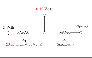
We can illustrate the way to find both resistors with a diagram:

If we run the equation for the above values (with Vi=5.00), we get:
|
R2 = 20000 × 0.19v / (5.00 - .19v) R2 = 20000 × 0.19v / (4.81v) R2 = 3800 / 4.81v R2 = 790ohms |
We can also solve for an unknown R1 (bias resistor) by changing the voltages around a little:
|
R1 = 790 × 4.81v / (5.00 - 4.81v) R1 = 790 × 4.81v / (0.19v) R1 = 3800 / 0.19v R1 = 20000 |
So now you know what the bias value is.
Here is a calculator for the bias resistor value: